本系列文已改編成書「Arduino 自造趣:結合 JavaScript x Vue x Phaser 輕鬆打造個人遊戲機」,本書改用 Vue3 與 TypeScript 全面重構且加上更詳細的說明,
在此感謝 iT 邦幫忙、博碩文化與編輯小 p 的協助,歡迎大家前往購書,鱈魚在此感謝大家 (。・∀・)。
若想 DIY 卻不知道零件去哪裡買的讀者,可以參考此連結 。( •̀ ω •́ )✧
再來就是實際建立透過 select 選擇的腳位,並建立相關 Firmata 功能。
稍微規劃一下預期 UI 內容。
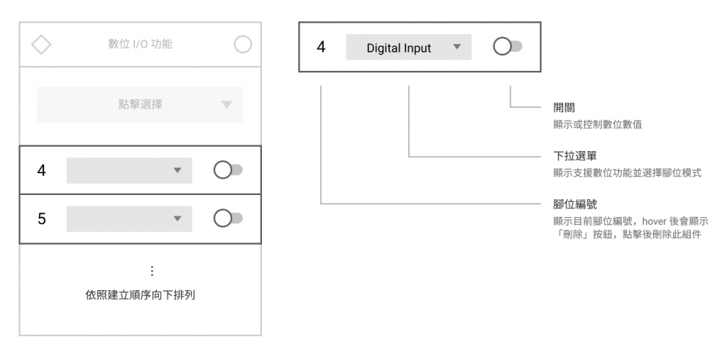
建立 window-digital-io-item.vue 組件,用來作為數位功能控制與顯示功能。
具體實現功能:
開關
使用 Quasar Toggle。
下拉選單
使用 Quasar Select。
顯示數位功能:Digital Input、Digital Output、Input Pullup
刪除按鈕(腳位編號)
使用 Quasar Button。
程式的部份為:
src\components\window-digital-io-item.vue <template lang="pug">
.c-row.q-0px.w-full
  .pin-number
    .text-20px
      | {{ pin.number }}
    q-btn.bg-white(
      @click='handleDelete',
      icon='r_delete',
      dense,
      flat,
      rounded,
      color='grey-5'
    )

  q-select.w-full(
    v-model='selectedCapabilitity',
    outlined,
    dense,
    rounded,
    emit-value,
    map-options,
    :options='capabilitityOptions',
    color='teal'
  )

  q-toggle(
    v-model='pinValue',
    color='teal-5',
    keep-color,
    checked-icon='r_bolt'
  )
src\components\window-digital-io-item.vue <style scoped lang="sass">
@import '@/styles/quasar.variables.sass'

.pin-number
  width: 36px
  padding: 10px 0px
  margin-right: 10px
  font-family: 'Orbitron'
  color: $grey
  text-align: center
  position: relative
  &:hover
    .q-btn
      pointer-events: auto
      opacity: 1
  .q-btn
    position: absolute
    top: 50%
    left: 50%
    transform: translate(-50%, -50%)
    pointer-events: none
    transition-duration: 0.4s
    opacity: 0
src\components\window-digital-io-item.vue <script>
/**
 * @typedef {import('@/script/modules/port-transceiver').default} PortTransceiver
 *
 * @typedef {import('@/types/type').PinInfo} PinInfo
 * @typedef {import('@/types/type').PinCapability} PinCapability
 */

import { mapState } from 'vuex';

import firmataUtils, { PinMode } from '@/script/utils/firmata.utils';

export default {
  name: 'WindowDigitalIoItem',
  components: {},
  props: {
    /** @type {PinInfo} */
    pin: {
      type: Object,
      required: true,
    },
  },
  data() {
    return {
      /** 數位功能種類 */
      digitalModes: [
        PinMode.DIGITAL_INPUT,
        PinMode.DIGITAL_OUTPUT,
        PinMode.INPUT_PULLUP,
      ],
      /** 選擇模式 */
      selectedCapabilitity: null,
      /** 腳位數值 */
      pinValue: false,
    };
  },
  computed: {
    ...mapState({
      /** @type {PortTransceiver} */
      portTransceiver: (state) => state.core.transceiver,
    }),

    /** 此腳位可用的模式 */
    usableCapabilities() {
      /** @type {PinInfo} */
      const pin = this.pin;

      const capabilities = pin.capabilities.filter((capabilitity) =>
        this.digitalModes.includes(capabilitity.mode)
      );

      return capabilities;
    },

    /** 腳位模式 select options */
    capabilitityOptions() {
      /** @type {PinCapability[]} */
      const usableCapabilities = this.usableCapabilities;

      return usableCapabilities.map((capabilitity) => {
        const { name: label } = firmataUtils.getDefineByCode(capabilitity.mode);

        return {
          label,
          value: capabilitity,
        };
      });
    },
  },
  watch: {},
  created() {},
  mounted() {},
  beforeDestroy() {},
  methods: {
    handleDelete() {},
  },
};
接著在 window-digital-io.vue 引入 window-digital-io-item.vue
src\components\window-digital-io.vue <script>
/**
 * @typedef {import('@/types/type').PinInfo} PinInfo
 */

import { mapState } from 'vuex';

import BaseWindow from '@/components/base-window.vue';
import BaseSelectPin from '@/components/base-select-pin.vue';
import WindowDigitalIoItem from '@/components/window-digital-io-item.vue';

//...

export default {
  name: 'WindowDigitalIo',
  components: {
    'base-window': BaseWindow,
    'base-select-pin': BaseSelectPin,
    'window-digital-io-item': WindowDigitalIoItem,
  },
  // ...
};
src\components\window-digital-io-item.vue <template lang="pug">
base-window.window-digital-io(
  :pos='pos',
  headerIconColor='teal-3',
  body-class='c-col p-20px pt-20px',
  title='數位 I/O 功能'
)
  base-select-pin(
    :pins='supportPins',
    color='teal-3',
    @selected='addPin',
    @err='handleErr'
  )

  q-scroll-area.pt-10px.h-300px.flex
    transition-group(name='list-complete', tag='div')
      window-digital-io-item.py-10px(
        v-for='pin in existPins',
        :pin='pin',
        :key='pin.number',
        @delete='deletePin'
      )
q-scroll-area 組件,保留未來滾動事件擴充性(文檔:Quasar Scroll Area)。transition-group 讓項目建立、移除時有過渡動畫。嘗試建立腳位看看。

出現了!ヾ(◍'౪`◍)ノ゙
再來就是實作數位功能了!
在控制腳位數值之前,需要先設定腳位模式。
在「Control Messages Expansion」可以找到設定腳位模式的命令為:
0  set digital pin mode (0xF4) (MIDI Undefined)
1  set pin number (0-127)
2  mode (INPUT/OUTPUT/ANALOG/PWM/SERVO/I2C/ONEWIRE/STEPPER/ENCODER/SERIAL/PULLUP, 0/1/2/3/4/6/7/8/9/10/11)
由以上說明可以得知:
0xF4
也就是說,如果要設定 Pin 11(0x0B)為「數位輸出(0x01)」模式,則命令為 [ 0xF4, 0x0B, 0x01 ]
接著根據剛才的結論,在 cmd-define.js 新增設定腳位模式命令。
src\script\firmata\cmd-define.js
export default [
  //...

	// setMode: 設定腳位模式
  {
    key: 'setMode',
    getValue({ pin, mode }) {
      const cmds = [0xF4, pin, mode];
      return cmds;
    },
  },
]
最後則是設定數位腳位數值,在「Control Messages Expansion」可以找到設定腳位數值的命令為:
0  set digital pin value (0xF5) (MIDI Undefined)
1  set pin number (0-127)
2  value (LOW/HIGH, 0/1)
由以上說明可以得知:
0xF5
也就是說,若要設定 Pin 11(0x0B)為「數位輸出數值」為:
0x01)」,則命令為 [ 0xF5, 0x0B, 0x01 ]
0x00)」,則命令為 [ 0xF5, 0x0B, 0x00 ]
接著根據剛才的結論,在 cmd-define.js 新增設定腳位模式命令。
src\script\firmata\cmd-define.js
export default [
  //...

	// setMode: 設定腳位模式
  {
    key: 'setMode',
    getValue({ pin, mode }) {
      const cmds = [0xF4, pin, mode];
      return cmds;
    },
  },

	// setDigitalPinValue: 設定數位腳位數值
  {
    key: 'setDigitalPinValue',
    getValue({ pin, value }) {
      const level = value ? 0x01 : 0x00;
      return [0xF5, pin, level];
    },
  },
]
在 window-digital-io-item.vue 中偵測選擇模式變化,進行腳位模式設定。
src\components\window-digital-io-item.vue <script>
/**
 * @typedef {import('@/script/modules/port-transceiver').default} PortTransceiver
 *
 * @typedef {import('@/types/type').PinInfo} PinInfo
 * @typedef {import('@/types/type').PinCapability} PinCapability
 */

import { mapState } from 'vuex';

import firmataUtils, { PinMode } from '@/script/utils/firmata.utils';

export default {
  name: 'WindowDigitalIoItem',
  // ...
  watch: {
    /** 偵測選擇的腳位功能 */
    selectedCapabilitity() {
      this.initMode();
    },
  },
  // ...
  methods: {
    // ...

    /** 初始化指定模式 */
    initMode() {
      /** @type {PinInfo} */
      const pin = this.pin;

      /** @type {PortTransceiver} */
      const portTransceiver = this.portTransceiver;

      /** @type {PinCapability} */
      const selectedCapabilitity = this.selectedCapabilitity;

      const mode = selectedCapabilitity.mode;

      portTransceiver.addCmd('setMode', {
        pin: pin.number,
        mode,
      });
    },
  },
};
只要使用者選定腳位功能後,就會發送 setMode 命令設定腳位模式。
再來就是偵測開關變化,並將開關數值傳送至腳位數值。
src\components\window-digital-io-item.vue <script>
/**
 * @typedef {import('@/script/modules/port-transceiver').default} PortTransceiver
 *
 * @typedef {import('@/types/type').PinInfo} PinInfo
 * @typedef {import('@/types/type').PinCapability} PinCapability
 */

import { mapState } from 'vuex';

import firmataUtils, { PinMode } from '@/script/utils/firmata.utils';

export default {
  name: 'WindowDigitalIoItem',
  // ...
  watch: {
		/** 偵測選擇的腳位功能 */
    selectedCapabilitity() {
      this.initMode();
    },

    pinValue(value) {
      /** @type {PinInfo} */
      const pin = this.pin;

      /** @type {PortTransceiver} */
      const portTransceiver = this.portTransceiver;

      portTransceiver.addCmd('setDigitalPinValue', {
        pin: pin.number,
        value,
      });
    },
  },
  // ...
};
實測看看有沒有發送成功。

使用兩個 LED 試試看。

感覺真棒 ✧*。٩(ˊᗜˋ*)و✧*。
上拉輸入與數位輸入都是數位訊號輸入,所以解析回應的地方都一樣,差別在腳位模式不同而已。
設定模式命令在數位輸出時已經完成,所以只差解析數位資料回應而已!
這時候有一個問題「所以要如何取得腳位數值?」,最直覺的想法是不斷發送查詢命令、取得數值,不過 Firmata 有個貼心的設計,可以讓 MCU 偵測腳位狀態變化,自動回傳狀態。
在「Message Types」找到 report digital port。
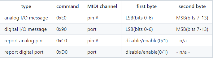
可以看到 report digital port 的命令為 0xD0,根據說明,可以得知:
0xD0 + port
實際上 Uno 操作腳位狀態是操作 Port Register 數值,每個 Port 之 Register 為 1 byte,所以可以控制 8 隻腳位狀態。
不過這裡的 port 並非實際上 Register 編號,單純是依順序分組。
例如:Pin 0 至 Pin 7 為 Port 0,Pin 8 至 Pin 15 為 Port 1,以此類推。
詳細內容可以查看以下連結:
Arduino CC - Port Manipulation
取得例子:
設定 Pin 4 為數位輸入。
Pin 4 為 Port 0,所以 [ 0xD0 + 0, 0x01 ],得命令為 [ 0xD0, 0x01 ]
設定 Pin 10 為數位輸入。
Pin 10 為 Port 1,所以 [ 0xD0 + 1, 0x01 ],得命令為 [ 0xD1, 0x01 ]
讓我們調整一下剛才 cmd-define.js 中的 setMode 命令,讓模式為數位輸入時,自動加入「開啟自動回報命令」。
src\script\firmata\cmd-define.js
import { PinMode } from '@/script/utils/firmata.utils';
const { DIGITAL_INPUT, INPUT_PULLUP } = PinMode;

export default [
  // ..

  // setMode: 設定腳位模式
  {
    key: 'setMode',
    getValue({ pin, mode }) {
      const cmds = [0xF4, pin, mode];

      // Mode 如果為 Digital Input,加入開啟自動回報命令
      if ([DIGITAL_INPUT, INPUT_PULLUP].includes(mode)) {
        const port = 0xD0 + ((pin / 8) | 0);
        cmds.push(port, 0x01);
      }

      return cmds;
    },
  },

  // ...
]
嘗試看看發送命令後,有沒有未定義的資料回應。

資料進來了!再來就是解析資料了。
在 response-define.js 新增定義 digitalMessage
src\script\firmata\response-define.js
/**
 * @typedef {import('@/types/type').DigitalResponseMessage} DigitalResponseMessage
 */

import { arraySplit, matchFeature } from '@/script/utils/utils';

export default [
  // ...

  // digitalMessage: 數位訊息回應
  {
    key: 'digitalMessage',
    eventName: 'data:digitalMessage',
    /**
     * @param {number[]} res
     */
    matcher(res) {

    },
    /**
     * @param {number[]} values
     * @return {DigitalResponseMessage[]}
     */
    getData(values) {

    },
  },
]
matcher() 和 getData() 內容要怎麼實作呢?在「Data Message Expansion」可以找到數位回應資料的說明:
Two byte digital data format, second nibble of byte 0 gives the port number (eg 0x92 is the third port, port 2)
回應資料為:
0  digital data, 0x90-0x9F, (MIDI NoteOn, bud different data format)
1  digital pins 0-6 bitmask
2  digital pin 7 bitmask
也就是說數值開頭只要包含 0x90-0x9F 就表示為數位資料回應,所以 matcher() 為:
/**
 * @typedef {import('@/types/type').DigitalResponseMessage} DigitalResponseMessage
 */

import { arraySplit, matchFeature } from '@/script/utils/utils';

export default [
  // ...

  // digitalMessage: 數位訊息回應
  {
    key: 'digitalMessage',
    eventName: 'data:digitalMessage',
    /**
     * @param {number[]} res
     */
		matcher(res) {
      const hasCmd = res.some((byte) => byte >= 0x90 && byte <= 0x9F);
      return hasCmd;
    },
    /**
     * @param {number[]} values
     * @return {DigitalResponseMessage[]}
     */
    getData(values) {

    },
  },
]
getData() 的部份則是如以下需求:
就是 D04 提到的「分屍傳輸」,將大於 ,1 byte 的數值拆分傳輸,現在則是要組裝回來。
所以先在 utils.js 建立一個專門組裝數值的函數。
src\script\utils\utils.js
// ...

/** 將有效 Bytes 轉為數值
 * @param {number[]} bytes 有效位元矩陣。bytes[0] 為 LSB
 * @param {number} [bitsNum] 每 byte 有效位元數
 */
export function significantBytesToNumber(bytes, bitsNum = 7) {
  const number = bytes.reduce((acc, byte, index) => {
    const mesh = 2 ** bitsNum - 1;

    const validBits = byte & mesh;
    acc += (validBits << (bitsNum * index))

    return acc;
  }, 0);

  return number;
}
bitsNum 參數預設 7接著完成 getData() 部份。
/**
 * @typedef {import('@/types/type').DigitalResponseMessage} DigitalResponseMessage
 */

import { arraySplit, matchFeature, significantBytesToNumber } from '@/script/utils/utils';

export default [
  // ...

  // digitalMessage: 數位訊息回應
  {
    key: 'digitalMessage',
    eventName: 'data:digitalMessage',
    /**
     * @param {number[]} res
     */
		matcher(res) {
      const hasCmd = res.some((byte) => byte >= 0x90 && byte <= 0x9F);
      return hasCmd;
    },
    /**
     * @param {number[]} values
     * @return {DigitalResponseMessage[]}
     */
		getData(values) {
      // 取得所有特徵點位置
      const indexs = values.reduce((acc, byte, index) => {
        if (byte >= 0x90 && byte <= 0x9F) {
          acc.push(index);
        }
        return acc;
      }, []);

      /** @type {DigitalResponseMessage[]} */
      const responses = indexs.reduce((acc, index) => {
        const bytes = values.slice(index + 1, index + 3);

        const port = values[index] - 0x90;
        const value = significantBytesToNumber(bytes);

        acc.push({
          port, value,
        });
        return acc;
      }, []);

      return responses;
    },
  },
]
最後在 window-digital-io-item.vue 加入 portTransceiver.on('data:digitalMessage'),接收看看資料。
src\components\window-digital-io-item.vue <script>
// ...

export default {
  name: 'WindowDigitalIoItem',
  // ...
  methods: {
    handleDelete() {},

    /** 初始化指定模式 */
    initMode() {
      // ...

      portTransceiver.addCmd('setMode', {
        pin: pin.number,
        mode,
      });

      portTransceiver.on('data:digitalMessage', (data) => {
        console.log(`[ digitalMessage ] data : `, ...data);
      });
    },
  },
};

成功接收資料!
最後來完善功能吧,首先 window-digital-io-item.vue 中的 initMode(),需要針對不同模式進行對應動作。
listener 儲存監聽器,並於組件銷毀或腳位模式切換時刪除監聽器。src\components\window-digital-io-item.vue <script>
// ...
const { DIGITAL_INPUT, DIGITAL_OUTPUT, INPUT_PULLUP } = PinMode;

export default {
  name: 'WindowDigitalIoItem',
	// ...
	data() {
    return {
			// ...
      listener: null,
    };
  },
  // ...
	beforeDestroy() {
    this.listener?.off?.();
  },
  methods: {
    handleDelete() {},

    /** 初始化指定模式 */
    initMode() {
      // ...

			/** @type {PinCapability} */
      const selectedCapabilitity = this.selectedCapabilitity;

      const mode = selectedCapabilitity.mode;

      portTransceiver.addCmd('setMode', {
        pin: pin.number,
        mode,
      });

			// 數位輸入
      if ([INPUT_PULLUP, DIGITAL_INPUT].includes(mode)) {
        this.listener = portTransceiver.on(
          'data:digitalMessage',
          (data) => {
            console.log(`[ digitalMessage ] data : `, ...data);
          },
          {
            objectify: true,
          }
        );
        return;
      }

      // 數位輸出
      if ([DIGITAL_OUTPUT].includes(mode)) {
        this.listener?.off?.();
        this.pinValue = false;
        return;
      }

      console.error(`[ initMode ] 未定義模式 : `, mode);
    },
  },
};
接著讓解析後的數位資料反映在開關上,有以下需求:
handleData(),負責處理接收到的資料並儲存至 pinValue。
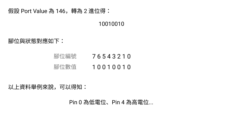
pinValue 數值。數位資料中的 value 是指整個 Port 的數值,也就是 8 隻腳的數值以二進位方式組合,關係如下圖:
在 utils.js 建立一個從數值中取得指定 bit 的函數。
src\script\utils\utils.js
// ...

/** 取得數值特定 Bit
 * @param {Number} number
 * @param {Number} bitIndex bit Index。從最小位元並以 0 開始
 */
export function getBitWithNumber(number, bitIndex) {
  const mesh = 1 << bitIndex;
  const value = number & mesh;
  return !!value;
}
依照需求設計程式。
src\components\window-digital-io-item.vue <script>
// ...
const { DIGITAL_INPUT, DIGITAL_OUTPUT, INPUT_PULLUP } = PinMode;

export default {
  name: 'WindowDigitalIoItem',
	// ...
	computed: {
    // ...

    /** 此腳位所屬的 Port 編號 */
    pinPortNum() {
      /** @type {PinInfo} */
      const pin = this.pin;
      const port = (pin.number / 8) | 0;

      return port;
    },
  },
	watch: {
    // ...

    pinValue(value) {
      /** @type {PinInfo} */
      const pin = this.pin;

      /** @type {PortTransceiver} */
      const portTransceiver = this.portTransceiver;

      // 只有輸出模式才要設定數值
      /** @type {PinCapability} */
      const { mode } = this.selectedCapabilitity;
      if (mode !== DIGITAL_OUTPUT) return;

      portTransceiver.addCmd('setDigitalPinValue', {
        pin: pin.number,
        value,
      });
    },
  },
	// ...
  methods: {
    // ...

		/** 初始化指定模式 */
    initMode() {
      // ...

      // 數位輸入
      if ([INPUT_PULLUP, DIGITAL_INPUT].includes(mode)) {
        this.listener = portTransceiver.on(
          'data:digitalMessage',
          (data) => {
            this.handleData(data);
          },
          {
            objectify: true,
          }
        );
        return;
      }

      // ...
    },

		/** 處理數值
     * @param {DigitalResponseMessage[]} data
     */
    handleData(data) {
      // 取得最後一次數值即可
      /** @type {DigitalResponseMessage} */
      const target = findLast(data, ({ port }) => {
        return this.pinPortNum === port;
      });

      if (!target) return;

      const { value } = target;

      /** @type {PinInfo} */
      const pin = this.pin;
      const bitIndex = pin.number % 8;

      this.pinValue = getBitWithNumber(value, bitIndex);
    },
  },
};
最後增加一點 UX 和其他細節:
src\components\window-digital-io-item.vue <script>
// ...
const { DIGITAL_INPUT, DIGITAL_OUTPUT, INPUT_PULLUP } = PinMode;

export default {
  name: 'WindowDigitalIoItem',
	// ...
	computed: {
		handleDelete() {
      this.$emit('delete', this.pin);
    },

    // ...

		/** 停用開關 */
    lockToggle() {
      /** @type {PinCapability} */
      const selectedCapabilitity = this.selectedCapabilitity;

      if (!selectedCapabilitity) {
        return true;
      }

      // 只有 OUTPUT 模式可以使用
      if (selectedCapabilitity.mode === DIGITAL_OUTPUT) {
        return false;
      }

      return true;
    },
  },
	// ..
};
src\components\window-digital-io-item.vue <template lang="pug">
.c-row.q-0px.w-full
  // ...

  q-toggle(
    v-model='pinValue',
    color='teal-5',
    keep-color,
    :disable='lockToggle',
    checked-icon='r_bolt'
  )
嘗試看看效果。

到此成功完成「數位 I/O 視窗」了!
以上程式碼已同步至 GitLab,大家可以前往下載:


 iThome鐵人賽