使用的python函式庫為:
sudo pip3 install adafruit-circuitpython-rgb-display
此函式庫為Adafruit推出的套件,並提供了範例原始碼如下:
import time
import busio
import digitalio
from board import SCK, MOSI, MISO, D2, D3

from adafruit_rgb_display import color565
import adafruit_rgb_display.ili9341 as ili9341


# Configuration for CS and DC pins:
CS_PIN = D2
DC_PIN = D3

# Setup SPI bus using hardware SPI:
spi = busio.SPI(clock=SCK, MOSI=MOSI, MISO=MISO)

# Create the ILI9341 display:
display = ili9341.ILI9341(spi, cs=digitalio.DigitalInOut(CS_PIN),
                          dc=digitalio.DigitalInOut(DC_PIN))

# Main loop:
while True:
    # Clear the display
    display.fill(0)
    # Draw a red pixel in the center.
    display.pixel(120, 160, color565(255, 0, 0))
    # Pause 2 seconds.
    time.sleep(2)
    # Clear the screen blue.
    display.fill(color565(0, 0, 255))
    # Pause 2 seconds.
    time.sleep(2)
我根據board類別得知 GPIO 參數設定如下:
 'CE0', 'CE1', 'D0', 'D1', 'D10', 'D11', 'D12', 'D13', 'D14', 'D15',
   8      7      0     1     10     11     12     13     14     15

 'D16', 'D17', 'D18', 'D19', 'D2', 'D20', 'D21', 'D22', 'D23', 'D24',
  16      17     18     19     2     20     21     22     23     24

 'D25', 'D26', 'D27', 'D3', 'D4', 'D5', 'D6', 'D7', 'D8', 'D9',
  25      26     27     3     4     5     6     7     8     9

 'I2C',                       'MISO', 'MISO_1', 'MOSI', 'MOSI_1',
 <function I2C at 0xb6564078>     9        19      10        20

 'RX', 'RXD', 'SCK', 'SCK_1', 'SCL', 'SCLK', 'SCLK_1', 'SDA',
  15     15     11       21      3      11        21      2

 'SPI',                       'TX', 'TXD',
 <function SPI at 0xb6564108>  14     14
呼叫busio.SPI物件確定了SCK, MOSI, MISO三個參數, 呼叫ili9341.ILI9341物件又確定了cs, dc此二個參數
# Setup SPI bus using hardware SPI:
spi = busio.SPI(clock=SCK, MOSI=MOSI, MISO=MISO)

# Create the ILI9341 display:
display = ili9341.ILI9341(spi, cs=digitalio.DigitalInOut(CS_PIN), dc=digitalio.DigitalInOut(DC_PIN))
翻開ili9341.ILI9341的初始設定, 確定rst設為None
def __init__(
        self,
        spi,
        dc,
        cs,
        rst=None,
        width=240,
        height=320,
        baudrate=16000000,
        polarity=0,
        phase=0,
        rotation=0,
    )
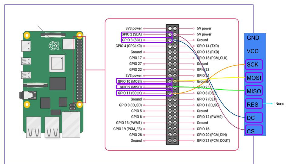
於是歸納結論 GPIO layout Setting如下:
SCK->11, MOSI->10, MISO->9, CS_PIN->2, DC_PIN->3, rst->None, 也就是如下圖模式:
接下來我的問題就來了, 如下圖, 購入的TFT模組並未特別註明SPI格式的接腳
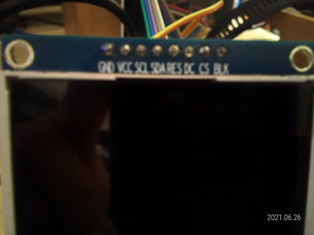
除了未標明MOSI, MISO外,SCK(SCL)是跟SDA作為I2C格式的搭配, 另一BL可同樣接5v或是不接, 同樣是八個針腳的ILI9341 TFT模組,電路格式不一定找得到統一的方法去做設定.
以下是最終測試成功後的GPIO接線Layout示意圖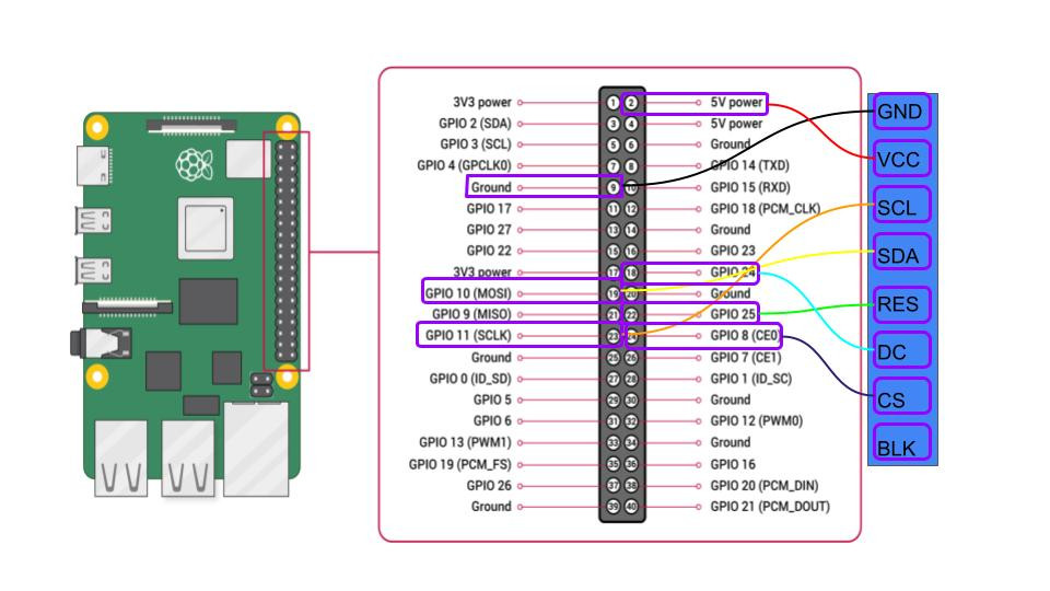
使用參考案例為https://jakew.me/2018/01/19/st7735-pi/的GPIOLayout
請注意以下:
定義以下 SCK, MOSI(SDA), D25(RS_PIN), D8(CS_PIN), D24(DC_PIN)from board import SCK, MOSI, D25, D8, D24
CS_PIN = D8
DC_PIN = D24
RS_PIN = D25
並在呼叫spi時省略MISOspi = busio.SPI(clock=SCK, MOSI=MOSI)
呼叫display時加上rst設定display = ili9341.ILI9341(spi, cs=digitalio.DigitalInOut(CS_PIN), dc=digitalio.DigitalInOut(DC_PIN), rst = digitalio.DigitalInOut(RS_PIN))
成果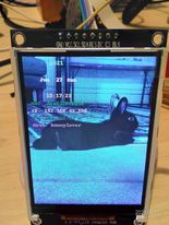
本篇原文來自https://github.com/KaliChen/ILI9341TFT240x320/blob/master/README.md
 KaliChen
