
最後一天就是要把大家領進門,
來把上回的智慧裝置串接到 Home Assistant ,
過去我們都使用 HTTP 來做各種育兒 IoT 應用,
今天則來試試 MQTT 這個更適合 IoT 的應用層網路傳輸協定,
並且使用 MQTT Broker 伺服器來收發工作。
首先要架設一個名為 MQTT Broker 的伺服器,
用來作為 智慧裝置 與 智慧平台 溝通的橋梁,
在本文使用 Eclipse Mosquitto 這套代理工具:
它已經有人包好可以直接用 Docker 啟動起來:
docker run -it -p 1883:1883 -p 9001:9001 eclipse-mosquitto
很簡單的一行我們擁有 MQTT Broker 了。
在撰寫客戶端韌體的部分也使用 MQTT 通訊,
需要使用 PubSubClient 來協助處理客戶端:
https://github.com/knolleary/pubsubclient
首先打開 Arduino IDE 選擇 工具 > 管理程式庫 ,
然後搜尋 PubSubClient 就可以找到程式庫並安裝:
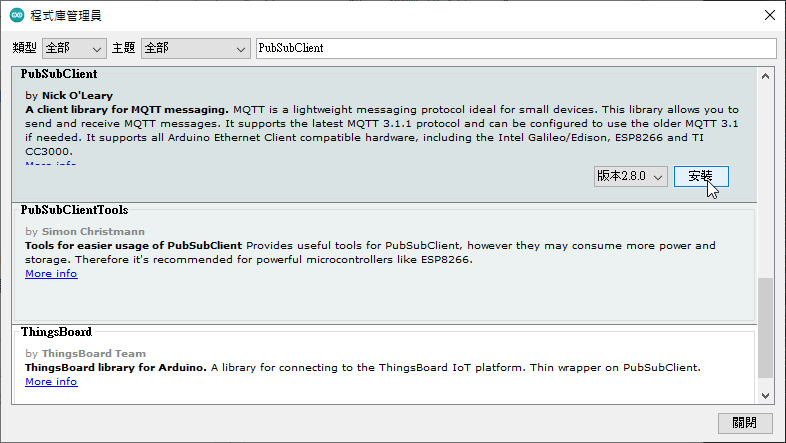
筆者這裡是使用 PubSubClient 的 ESP8266 來修改的:
https://github.com/knolleary/pubsubclient/blob/master/examples/mqtt_esp8266/mqtt_esp8266.ino
連線方面增加了 mqtt_name 、 mqtt_password 提供連線使用,
狀態部分將 msg 設定為 1 或 0 提供 HA 燈號的狀態:
snprintf(msg, MSG_BUFFER_SIZE, "%ld", 1);
同樣的韌體程式語法在此不作細部說明,
完整程式碼如下:
#include <ESP8266WiFi.h>
#include <PubSubClient.h>

// Update these with values suitable for your network.

const char *ssid = "SSID名稱";
const char *password = "Wifi密碼";
const char *mqtt_server = "MQTT伺服器Host";
const char *mqtt_name = "連線名稱";
const char *mqtt_password = "連線密碼";

WiFiClient espClient;
PubSubClient client(espClient);
unsigned long lastMsg = 0;
#define MSG_BUFFER_SIZE (50)
char msg[MSG_BUFFER_SIZE];
int value = 0;

void setup_wifi()
{

    delay(10);
    // We start by connecting to a WiFi network
    Serial.println("");
    Serial.print("Connecting to ");
    Serial.println(ssid);

    WiFi.mode(WIFI_STA);
    WiFi.begin(ssid, password);

    while (WiFi.status() != WL_CONNECTED)
    {
        delay(500);
        Serial.print(".");
    }

    randomSeed(micros());

    Serial.println("");
    Serial.println("WiFi connected");
    Serial.println("IP address: ");
    Serial.println(WiFi.localIP());
}

void callback(char *topic, byte *payload, unsigned int length)
{
    Serial.print("Message arrived [");
    Serial.print(topic);
    Serial.print("] ");
    for (int i = 0; i < length; i++)
    {
        Serial.print((char)payload[i]);
    }
    Serial.println();

    // Switch on the LED if an 1 was received as first character
    if ((char)payload[0] == '1')
    {
        digitalWrite(BUILTIN_LED, LOW); // Turn the LED on (Note that LOW is the voltage level
        // but actually the LED is on; this is because
        // it is active low on the ESP-01)
        snprintf(msg, MSG_BUFFER_SIZE, "%ld", 1);
    }
    else
    {
        digitalWrite(BUILTIN_LED, HIGH); // Turn the LED off by making the voltage HIGH
        snprintf(msg, MSG_BUFFER_SIZE, "%ld", 0);
    }
}

void reconnect()
{
    // Loop until we're reconnected
    while (!client.connected())
    {
        Serial.print("Attempting MQTT connection...");
        // Create a random client ID
        String clientId = "ESP8266Client-";
        clientId += String(random(0xffff), HEX);
        // Attempt to connect
        if (client.connect(clientId.c_str(), mqtt_name, mqtt_password))
        {
            Serial.println("connected");
            // Once connected, publish an announcement...
            client.publish("outTopic", "0");
            // ... and resubscribe
            client.subscribe("inTopic");
        }
        else
        {
            Serial.print("failed, rc=");
            Serial.print(client.state());
            Serial.println(" try again in 5 seconds");
            // Wait 5 seconds before retrying
            delay(5000);
        }
    }
}

void setup()
{
    pinMode(BUILTIN_LED, OUTPUT); // Initialize the BUILTIN_LED pin as an output
    Serial.begin(115200);
    setup_wifi();
    client.setServer(mqtt_server, 1883);
    client.setCallback(callback);
}

void loop()
{
    if (!client.connected())
    {
        reconnect();
    }
    client.loop();

    unsigned long now = millis();
    if (now - lastMsg > 2000)
    {
        lastMsg = now;
        ++value;
        Serial.print("Publish message: ");
        Serial.println(msg);
        client.publish("outTopic", msg);
    }
}
由於 Home Assistant 也需要連線至 MQTT Broker ,
因此在 configuration.yaml 設定好如下範例:
mqtt:
  broker: 192.168.1.108
  username: 連線名稱
  password: 連線密碼
設定好後 HA 就能自動與 Eclipse Mosquitto 連線。
最後是智慧裝置的控制及介面設定,
這裡建立一個 switch 用來控制燈號,
如下範例:
switch:
  - platform: mqtt
    name: "light"
    icon: mdi:lightbulb-outline
    command_topic: "inTopic"
    state_topic: "outTopic"
    qos: 1
    payload_on: "1"
    payload_off: "0"
    retain: true
都配置完畢後總覽就會出現開關囉!
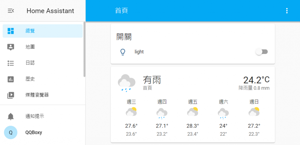
完成了所有的配置之後,
這就是最後成功運作的畫面啦

由於我們使用的是 Windwos 的 Docker ,
架設的 HA 智慧家庭平台是沒有 Supervisor 的,
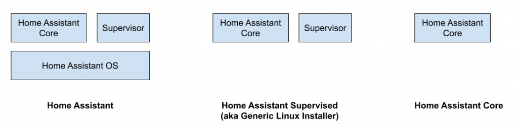
所以會無法使用 Add-on Store 來安裝 Mosquitto,
因此本文直接使用 Docker 架設 Eclipse Mosquitto 。



 iThome鐵人賽
 看影片追技術