經過前兩天的環境準備,我們就來試著讓ESP32開發板上內建的LED燈閃爍,熟悉一下如何在VS Code中開啟範例程式、上傳燒錄到開發板。對Arduino和ESP32還不瞭解也沒關係,因為今天只會用到Arduino提供的範例程式,順便讓大家先觀察一下Arduino的程式架構是如何組成的,明天再來解釋程式架構,並教大家如何自己新建專案。後天開始就會介紹Arduino和ESP32的科普小知識及相關函式~
先來練習開起範例程式吧!我們今天要開的範例程式是Arduino內建好的Blink(閃爍),如果你是要用Arduino IDE開起的話,他會放在檔案->範例->01.Basics底下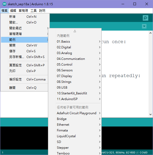
如果你是用VS Code的話,請使用「F1」、「CTRL+SHIFT+P」來開啟命令面板,並使用 Arduino: Examples 命令來開啟範例資料夾,如果找不到命令的話,可以先輸入「Arduino」來快速找到指令,你常用的指令會放在越上方~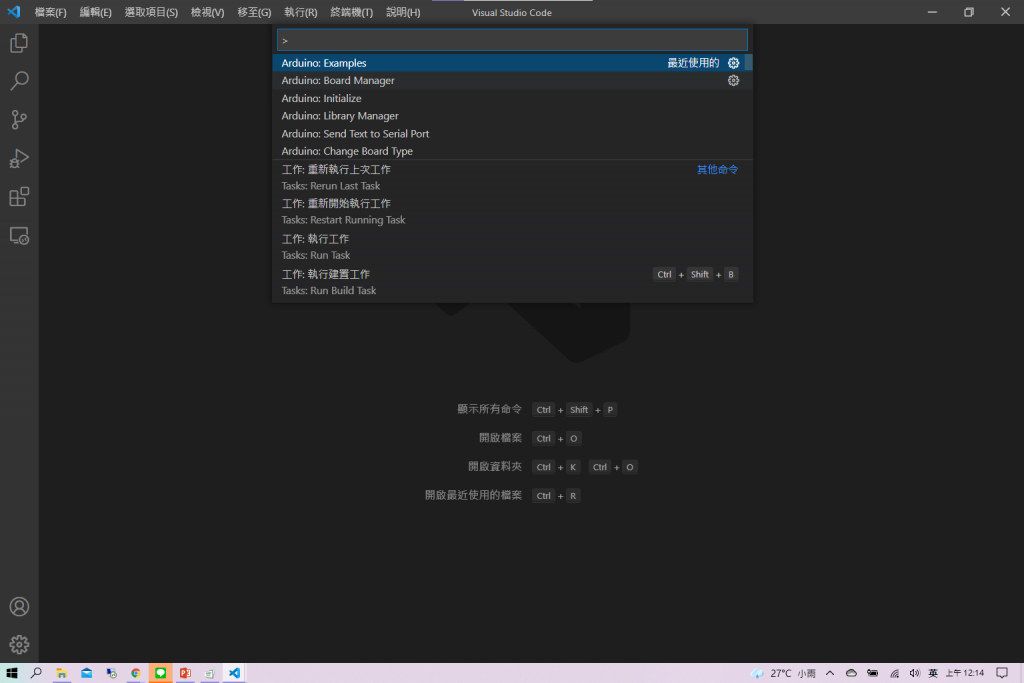
將 Arduino: Examples 點下去之後就會跳出一個範例資料夾分頁,Built-in Examples 裡放的是Arduino內建範例程式,其實就跟從Arduino IDE打開是一樣的意思噢!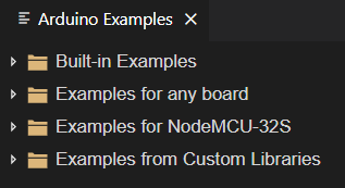
Blink一樣放在 Built-in Examples ->01.Basics底下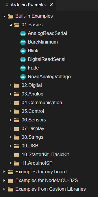
Blink點開後就會向下面程式碼一樣
/*
  Blink

  Turns an LED on for one second, then off for one second, repeatedly.

  Most Arduinos have an on-board LED you can control. On the UNO, MEGA and ZERO
  it is attached to digital pin 13, on MKR1000 on pin 6. LED_BUILTIN is set to
  the correct LED pin independent of which board is used.
  If you want to know what pin the on-board LED is connected to on your Arduino
  model, check the Technical Specs of your board at:
  https://www.arduino.cc/en/Main/Products

  modified 8 May 2014
  by Scott Fitzgerald
  modified 2 Sep 2016
  by Arturo Guadalupi
  modified 8 Sep 2016
  by Colby Newman

  This example code is in the public domain.

  https://www.arduino.cc/en/Tutorial/BuiltInExamples/Blink
*/

// the setup function runs once when you press reset or power the board
void setup() {
  // initialize digital pin LED_BUILTIN as an output.
  pinMode(LED_BUILTIN, OUTPUT);
}

// the loop function runs over and over again forever
void loop() {
  digitalWrite(LED_BUILTIN, HIGH);   // turn the LED on (HIGH is the voltage level)
  delay(1000);                       // wait for a second
  digitalWrite(LED_BUILTIN, LOW);    // turn the LED off by making the voltage LOW
  delay(1000);                       // wait for a second
}
接下來,確認你已經選擇了正確的開發板型號和序列埠,如果還沒選擇可以直接點選照片中的位置就可以設定!我這裡是用NodeMCU-32S搭配COM3,後續直接點右上角「上傳Upload」圖示進行驗證與上傳的動作。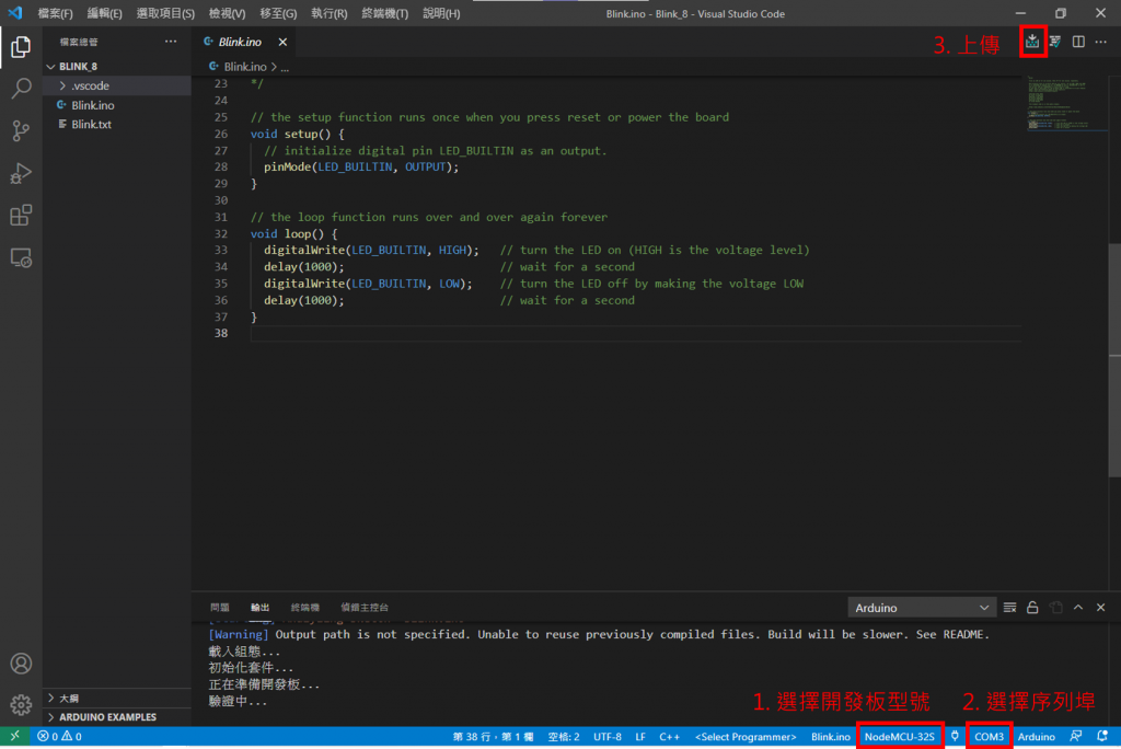
另外,DOIT ESP32 DEVKIT V1 這塊開發板在上傳時有個小坑,我當初不知道就踩了進去,但我們後天再來仔細說QQ總之,如果你手上是這個型號的開發板的話,記得在輸出視窗跑出 Connecting...--... 時要一直按住板子上的 BOOT 按鈕,才能成功上傳!驗證時會花一點時間檢查語法,完成後就會開始上完囉!
以下是上傳成功畫面
不知道大家有沒有覺得範例程式的字看起來很多呢?但其實大部分都是註解而已XD對C++熟悉的人應該對註解不陌生,下面三種都是C++中可行的註解噢!
//1.我是一行註解

/*2.我也是一行註解*/

/*3.我是一行被分段
                    的註解*/
所以其實真正的程式碼只有以下的部分而已
void setup() {
  // initialize digital pin LED_BUILTIN as an output.
  pinMode(LED_BUILTIN, OUTPUT);
}

// the loop function runs over and over again forever
void loop() {
  digitalWrite(LED_BUILTIN, HIGH);   // turn the LED on (HIGH is the voltage level)
  delay(1000);                       // wait for a second
  digitalWrite(LED_BUILTIN, LOW);    // turn the LED off by making the voltage LOW
  delay(1000);                       // wait for a second
}
以C++控制的硬體程式架構,是由setup()、loop() 兩大函式組成,缺一不可。裏頭的其他函示會依照之後的主題慢慢帶,敬請期待。
那兩者的差異,我賣個關子留到明天再說,大家可以先從字面上的意思去瞭解兩者的不同 (絕對不是要拖天數)
所以明天就是會把程式架構的說明補充完,並教大家如何在VS Code新建自己的Blink專案!


 iThome鐵人賽